AVDF
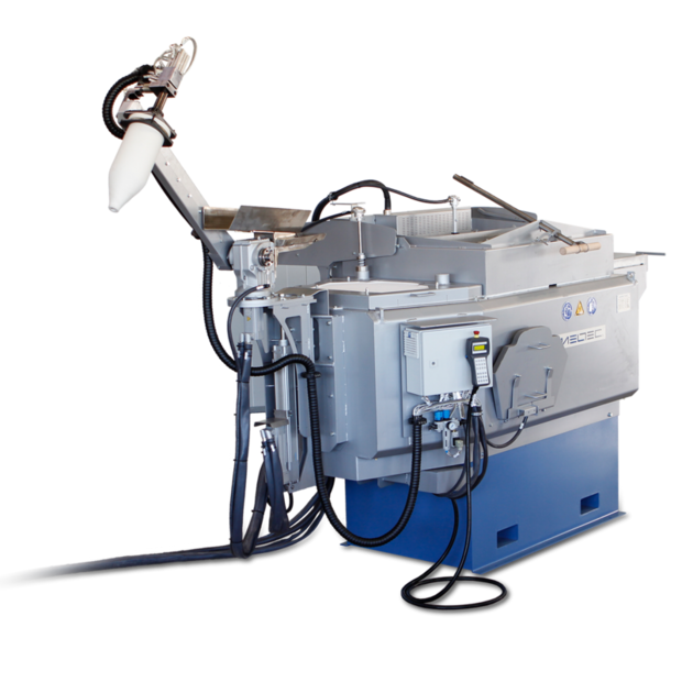
Aluminium Vacuum Dosing Furnace
The tank furnaces are designed for holding aluminum die-cast alloys. Refractory lining and high-quality rear insulation result in very low energy consumption and therefore low operating costs. The longevity of the tank and easy cleaning are further advantages of this structure. The heating is provided by the heating elements integrated in the top lid, which are characterized by their performance and service life. The heating elements are controlled via thyristors, which keep the melt at the right temperature without overheating. Due to the fact that the cover can be easily opened, there is very good access to the tank and the care of the melt is easy. For the highest demands on the melt, the tank furnaces are equipped with several chambers. Thus, the melt can be removed in high quality.
In addition, flushing plugs can be installed in the calming zone for melt treatment. Purge gases flow through these porous materials, ensuring even gas distribution. The melt is degassed in the process, thus ensuring the low density index.
Optionally, the holding furnace can be operated with a hydraulic tilting unit for easy alloy changes.
The dosing system consists of a vacuum ceramic container, an evacuation device for sucking in the melt and a special closure at the suction point. The vacuum ceramic container is made of a non-sticking, temperature change-resistant and solid ceramic. The mechanical movement takes place via a servo-controlled lifting and swiveling device.
The system shows the following advantages:
- Take in of melt below bath level – less oxides
- Filling of container by sucking in melt – less oxides
- Transfer of melt without air admission – less oxides
- Transfer of melt into a closed ceramic container – low drop of temperature
- High dosing accuracy through integrated, precise quantity measurement
- Energy-efficient, precise holding and dosing for the highest alloy qualities
Technical data
AVDF - Aluminium Vacuum Dosing Furnace
| AVDF | usable tank contents [kg] | heating capacity [kW] | recommended dosing system sizes |
|---|---|---|---|
| 600 | 400 | 21 | VDU1000 - VDU3000 |
| 900 | 600 | 24 | VDU3000 - VDU5000 |
| 1200 | 900 | 24 | VDU5000 - VDU10K |
| 1800 | 1200 | 28 | VDU10K - VDU25K |
| 2800 | 1800 | 32 | VDU25K - VDU60K |
| VDU | recommended dosing amounts [g] | dosing accuracy [g] * |
|---|---|---|
| 1000 | 100 - 1000 | ± 10 |
| 2500 | 750 - 2500 | ± 15 |
| 3000 | 900 - 3000 | ± 15 |
| 5000 | 1500 - 5000 | ± 25 |
| 10k | 4000 - 10000 | ± 35 |
| 15k | 6000 - 15000 | ± 45 |
| 20k | 8000 - 20000 | ± 60 |
| 40k | 12000 - 40000 | ± 100 |
| 60k | 18000 - 60000 | ± 150 |


